
Heat Pump System: Major Components & Functions
(Applies to Air-Source & Ground-Source Systems – Focus on Core Refrigeration Circuit)
- Compressor:
- Function: The “heart” of the system. Takes low-pressure, low-temperature refrigerant vapor from the evaporator and compresses it into a high-pressure, high-temperature vapor. This compression significantly increases the refrigerant’s energy level.
- Common Types: Scroll (most common), Rotary, Reciprocating (older).
- Potential Repair Issues: Motor burnout (electrical failure), mechanical seizure (lack of lubrication, contamination), faulty internal valves, capacitor failure (prevents starting), vibration/noise. Requires specialized tools and EPA certification to replace due to refrigerant handling.
- Condenser Coil:
- Function: Acts as the heat rejector.
- In HEATING Mode: Located outdoors (for ASHP) or in the building (for GSHP/WSHP). Hot, high-pressure refrigerant gas from the compressor flows through it. A fan (ASHP) or water pump (GSHP/WSHP) moves cooler air/water across the coil, causing the refrigerant to release heat and condense into a liquid.
- In COOLING Mode: Located outdoors (ASHP) or in the ground loop/water (GSHP/WSHP). Releases the heat absorbed from indoors plus compressor heat to the outside environment.
- Construction: Copper tubing with aluminum fins (ASHP) or often copper-nickel or specialized tubing (GSHP/WSHP) for corrosion resistance.
- Potential Repair Issues: Physical damage (bent fins), corrosion (especially coastal), refrigerant leaks (at fittings or damaged tubing), clogging (dirt, leaves, pollen on ASHP; mineral scale in WSHP), fan motor failure (ASHP).
- Function: Acts as the heat rejector.
- Evaporator Coil:
- Function: Acts as the heat absorber.
- In HEATING Mode: Located outdoors (ASHP) or in the ground loop/water (GSHP/WSHP). Cold, low-pressure liquid refrigerant flows through it. Outdoor air (ASHP) or ground/water (GSHP/WSHP) moves across the coil, causing the refrigerant to absorb heat and evaporate into a gas.
- In COOLING Mode: Located indoors (in the air handler). Absorbs heat from the warm indoor air passing over it, cooling the air and evaporating the refrigerant.
- Construction: Similar to Condenser Coil (copper/aluminum fins).
- Potential Repair Issues: Refrigerant leaks (common at joints), ice buildup (low refrigerant, airflow restriction), physical damage, dirt/dust clogging (indoor coil), mold growth (indoor coil – requires cleaning).
- Function: Acts as the heat absorber.
- Expansion Device / Metering Device:
- Function: Creates a pressure drop between the high-pressure liquid line (from condenser) and the low-pressure evaporator. This sudden pressure drop causes the liquid refrigerant to rapidly cool (“flash”) as it enters the evaporator coil. Controls the precise flow rate of refrigerant into the evaporator.
- Common Types:
- Thermostatic Expansion Valve (TXV): Most common. Uses a temperature-sensing bulb on the evaporator outlet to modulate refrigerant flow based on superheat. More precise than fixed orifices.
- Electronic Expansion Valve (EEV): Increasingly common. Controlled by the system’s microprocessor for even greater precision, especially in inverter systems.
- Fixed Orifice / Piston: Simpler, less expensive, less precise fixed restriction. Found in some basic systems.
- Potential Repair Issues: Clogging (debris, wax), stuck open/closed (TXV), power/signal failure (EEV), incorrect superheat setting (TXV). Often requires recovery/recharge to replace.
- Reversing Valve (4-Way Valve):
- Function:Key component for HEAT/COOL changeover. It’s a solenoid-controlled valve that redirects the flow of refrigerant, effectively swapping the roles of the indoor and outdoor coils.
- In HEATING Mode: Directs hot gas from compressor to the indoor coil (making it the condenser). Directs gas from outdoor coil (evaporator) back to compressor.
- In COOLING Mode: Directs hot gas from compressor to the outdoor coil (condenser). Directs gas from indoor coil (evaporator) back to compressor.
- Potential Repair Issues: Solenoid coil failure (electrical), valve sticking (mechanical – can cause short cycling, lack of mode change, weird noises), refrigerant leaks (at body or tubing connections). Requires refrigerant recovery/recharge to replace.
- Function:Key component for HEAT/COOL changeover. It’s a solenoid-controlled valve that redirects the flow of refrigerant, effectively swapping the roles of the indoor and outdoor coils.
- Accumulator:
- Function: A tank located on the suction line (low-pressure gas returning to compressor) before the compressor. Protects the compressor from liquid refrigerant “slugging” (which can destroy it) by allowing any liquid to boil off into vapor before entering the compressor. More common on heat pumps due to wider operating conditions.
- Potential Repair Issues: Refrigerant leaks (welds, fittings). Rarely fails internally unless severely contaminated.
- Filter Drier:
- Function: A canister containing desiccant (drying material) and a filter screen. Located in the liquid line (high-pressure liquid going to expansion device). Removes moisture and contaminants from the refrigerant circuit, preventing acid formation, ice blockages, and component damage.
- Potential Repair Issues: Clogging (restricts flow, causes high head pressure), saturation (stops absorbing moisture). Must be replaced any time the system is opened to the atmosphere or after a compressor burnout. Requires recovery/recharge.
Essential Supporting Components:
- Refrigerant: The specialized fluid (e.g., R-410A, R-32, R-454B) that circulates through the closed loop, changing state (liquid/gas) to absorb and release heat. Handling requires EPA 608 Certification.
- Indoor Air Handler / Blower Unit: Contains the evaporator coil (in cooling mode), blower fan, air filter, and often auxiliary electric heat strips. Circulates conditioned air through ducts.
- Outdoor Unit (ASHP): Houses the compressor, condenser coil (in heating mode), fan, reversing valve, accumulator, and often the expansion device. Designed for weather exposure.
- Ground Loop (GSHP): Buried piping (closed loop with antifreeze/water mix or open well water system) that exchanges heat with the earth. Includes circulation pump(s).
- Defrost Control Board & Sensors (ASHP): Critical for cold climates. Monitors outdoor coil temperature and activates a defrost cycle (temporarily switching to cooling mode to melt ice on the outdoor coil) when needed. Malfunction leads to ice buildup and loss of heating.
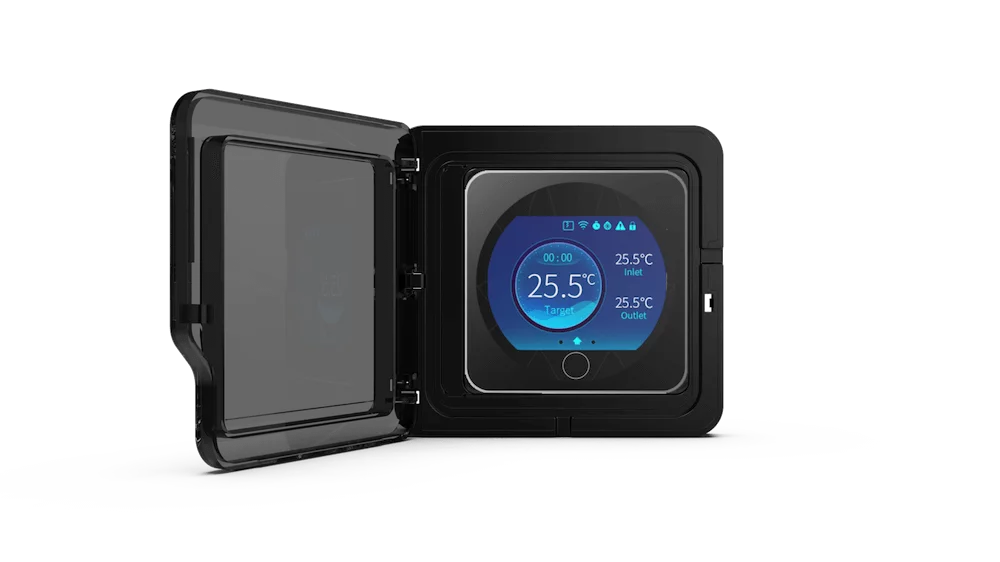
- Thermostat / Control System: The user interface and brain. Signals the system when to run, in which mode (heat/cool), and at what capacity. Communicates with sensors and control boards.
- Auxiliary/Emergency Heat Strips (ASHP): Electric resistance heating elements (like a large hair dryer) located in the indoor air handler. Provide heat when the heat pump can’t keep up (extreme cold) or during defrost cycles. Significant energy users.
Key Takeaway for Repair: Diagnosing a heat pump problem requires understanding which component is likely failing based on symptoms (e.g., no heat, poor cooling, strange noises, ice buildup) and system pressures/temperatures. Crucially, work involving the sealed refrigerant circuit (compressor, coils, valves, lines) MUST be performed by a licensed HVAC technician with proper certification and equipment. Tasks like cleaning coils or replacing air filters are typical homeowner maintenance.